Innovation in Design & Engineering
Mechanical engineer / cofounder Ron Weingart explains the process of developing the revolutionary, patented design.
“I was presented with the challenge of designing an in-line sprinkler fertigation system. I studied what was currently available for residential use and most designs were in-ground, cumbersome devises. Every unit I came across required a time-consuming installation including digging up a big hole in the yard, cutting the sprinkler pipes and plumbing, and adding new, complex fittings. My goal was to design a simple, easy-to-install devise capable of dispensing both liquid and solid chemicals.”
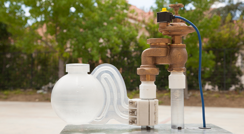
My concept was based on Bernoulli’s Principle which, for purposes of my design, is simply the creation of a lower pressure area by the flow of water in the sprinkler pipe past a discharge nozzle so that the chemical could be sucked into the sprinkler line from a piggy-back devise attached to the pipe. The concept was expanded to include a ram intake nozzle to facilitate and speed up the flow of water through the reservoir in order for the chemical to be more quickly mixed and fed through the sprinklers over the course one typical sprinkler cycle.

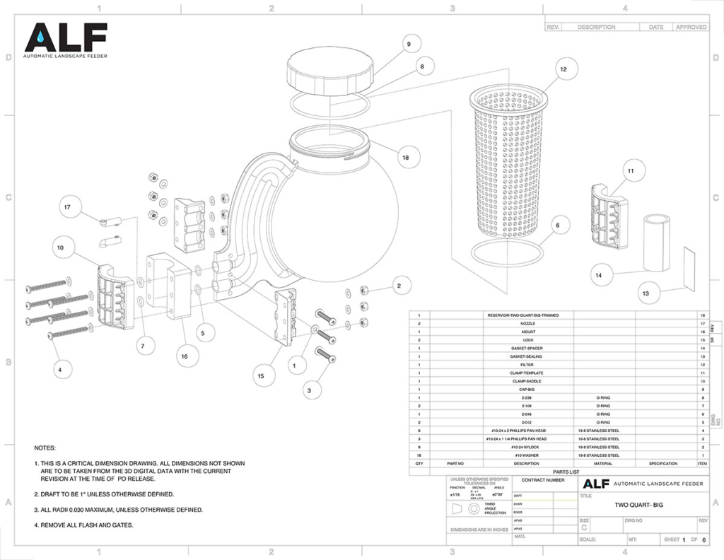
I wanted a unit that was both easy to install and to remove if needed without disrupting the owner’s sprinkler system. I used the saddle clamp concept to attach the unit to the sprinkler pipe requiring only two drilled holes in the pipe for the intake and discharge nozzles. A provided template clamp is clamped in place with the saddle clamp provided so that the holes can be easily drilled in the correct location minimizing installer mistakes and mislocating the holes, a common experience using paper templates, and all but eliminating drill bit wandering. The unit was designed to fit as close as 2-1/2″ below the sprinkler valve and the template clamp ensures that the installer correctly locates the unit. The saddle clamp can be positioned over the drilled holes and clamped in place with the template to seal the holes in the sprinkler pipe if the user wants to remove the unit without disrupting use of the sprinkler system.
The sprinkler valve discharge line location was selected so that the installer need not shut off the water supply assuming that the sprinkler valve was not turned on. This also allowed for one unit per sprinkler zone so that the different chemicals could be fed zone by zone as desired and for only those zones for which chemical was desired.
The reservoir was designed as a sphere for both strength under pressure and for ready mixing of the chemical with the sprinkler water. The design of the discharge nozzle outlet tube was to eliminate the need for a valve to prevent the escape of chemical into the sprinkler line while filling.
Most sprinkler systems are either 3/4″ or 1″ pipe and the unit was designed to fit either size pipe so the user wouldn’t have to determine which size pipe they had. A simple rubber spacer gasket fits over the 3/4″ pipe if needed.
An optional basket can be placed in the reservoir for user desiring to use solid chemical which dissolves into solution with the sprinkler water flowing through the reservoir and then dispensed through the sprinklers.
Many sprinkler zones cover approximately 800 to 1,000 square feet and the application rate for many liquid chemicals is one quart per 1,000 square feet so a one quart reservoir capacity was designed for liquid only chemical units. A larger two quart reservoir design is for larger size sprinkler zones or for use with chemicals having a greater application rate. The two quart reservoir was designed in two versions, one with a smaller filler for liquid chemical only and the other with a larger filler for use with (or without) the optional solid chemical basket. These sizes were selected so that the typical application could be achieved in one sprinkler cycle and that different chemicals could be dispensed as desired without having to empty out any unused chemical.
Simplicity was the goal in not only installation or removal but use and maintenance as well. Use simply consists of filling the reservoir with the appropriate amount of chemical for the area and screwing on the filler cap tightly. Nothing else is required. The unit will begin dispensing the chemical when the sprinkler valve is turned on. Normal maintenance consists of nothing more than occasionally washing out the reservoir of, if any, chemical residue by flushing out with a garden hose.”
*Engineering Note: ALF is completely engineered with both stp and stl files and requires only your logo to begin manufacturing.

